Multi-robot timber fabrication setup and process
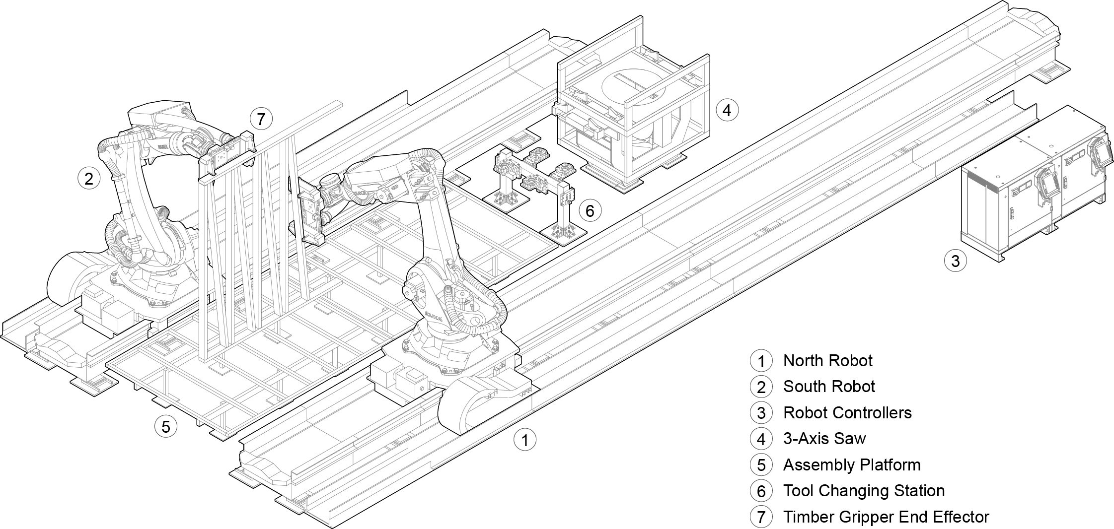
Our fabrication setup (Fig. 1) comprises two six-axis industrial robotic arms with a payload of 120 kg and a reach of 2700 mm, mounted on parallel linear tracks. Each robotic arm has access to an automatic tool-changing station, which enables seamless end-effector swapping. In our experiments, each robotic arm utilizes a custom pneumatically controlled gripper end effector to grasp lumber elements with varying profile dimensions (e.g., nominal 2×4 or 4×6). Additionally, we used a 2D laser profiler3 for all scanning operations (e.g., scanning the as-built subassembly), and the robotic arms swapped out their grippers with this laser profiler whenever necessary during the fabrication process. We also designed, engineered, and built a three-axis CNC saw and mounted it between the two tracks to be accessible by both robots. The saw has a blade with a radius of 300 mm and a kerf of 6.25 mm. The saw blade can rotate -180 to +180 degrees and tilt between 0 and 45 degrees, enabling perpendicular cuts as well as a wide range of miter and compound miter cuts.
Bi-directional digital design-to-fabrication workflow
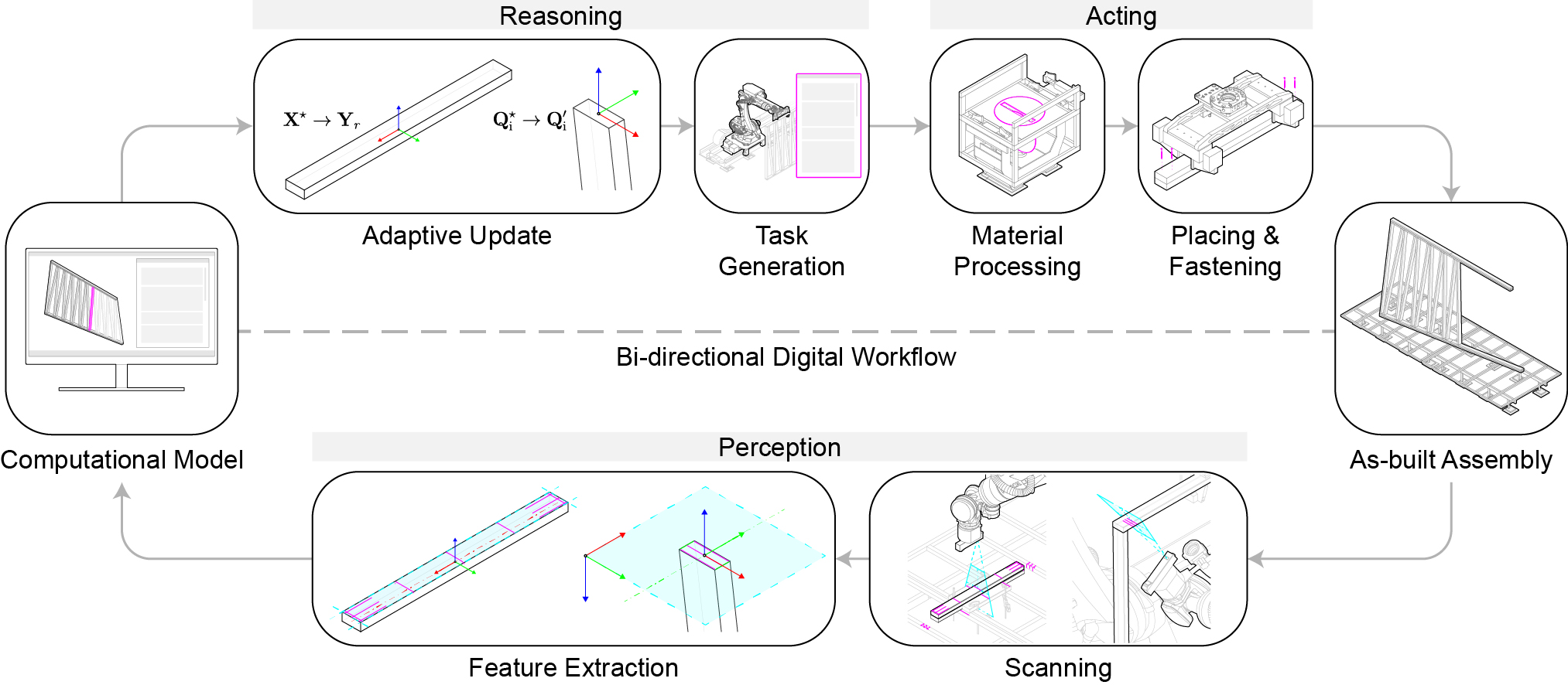
The bi-directional digital design-to-fabrication workflow (Fig.2) is implemented as a loop, including a forward and a backward process. The forward process derives the necessary poses and cut parameters from the digital model of each timber element, which our control algorithm can interpret for trajectory planning, saw configuration, and gripper state. The planned trajectory, saw configuration, and gripper states are then automatically post-processed into KUKA Robot Language (KRL) code to be executed by the robotic arms and the CNC saw. The backward workflow process facilitates the necessary feedback into the as-planned digital model based on perceived as-built conditions and enables adaptive correction of the as-planned model for future fabrication steps. We investigated and tested two adaptive methods for our framework: pose-based and topology-based adaptive fabrication.
Pose-based adaptive fabrication
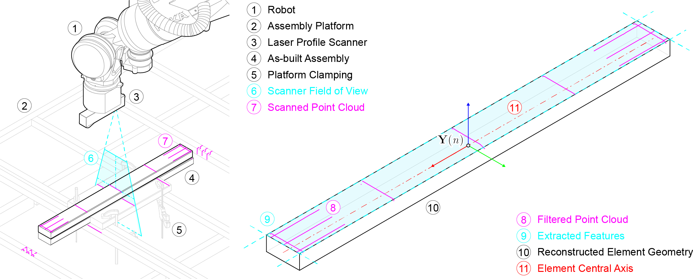
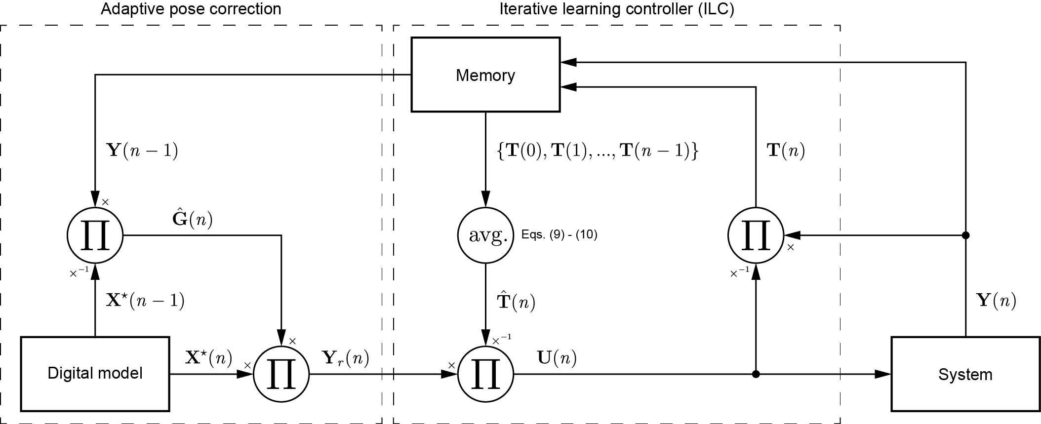
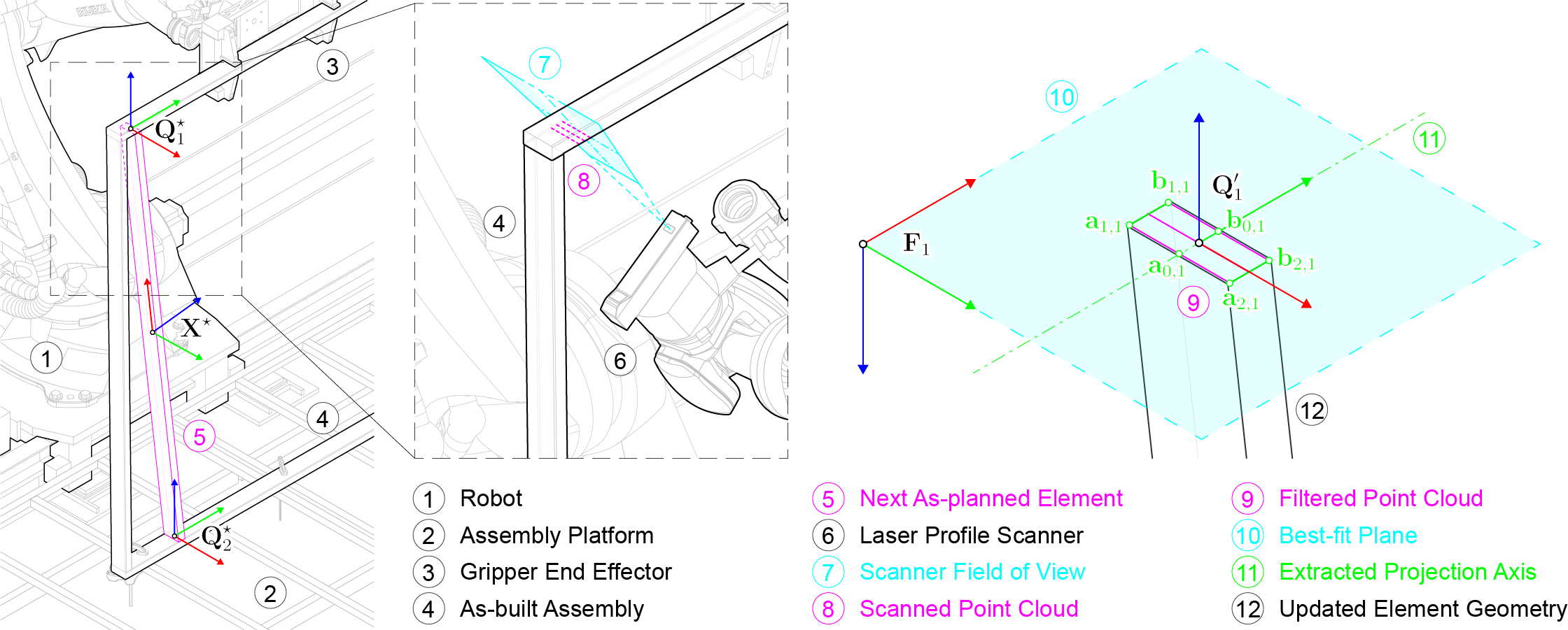
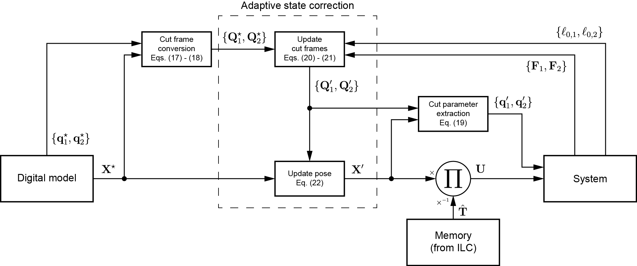
By tracking element poses, we formalize an adaptive fabrication method for minimizing deviations between the as-planned digital model and the as-built subassembly. We first formalize the fabrication process into a state-space representation, which sets the foundation for both adaptive methods. We then expand on how a robot perceives a pose by scanning the element extents and reconstructing the element geometry (Fig. 3). Next, we implement a direct Iterative Learning Control (ILC) algorithm to minimize the tracking error between the reference and perceived poses, which iteratively self-corrects for any fabrication inaccuracies in the robotic setup. Finally, we develop the method for adaptively updating an element’s reference pose based on the current as-built conditions, enabling multi-robot coordination with a common localization reference. The overall control process is visualized in Fig. 4.
NLT panel experiment
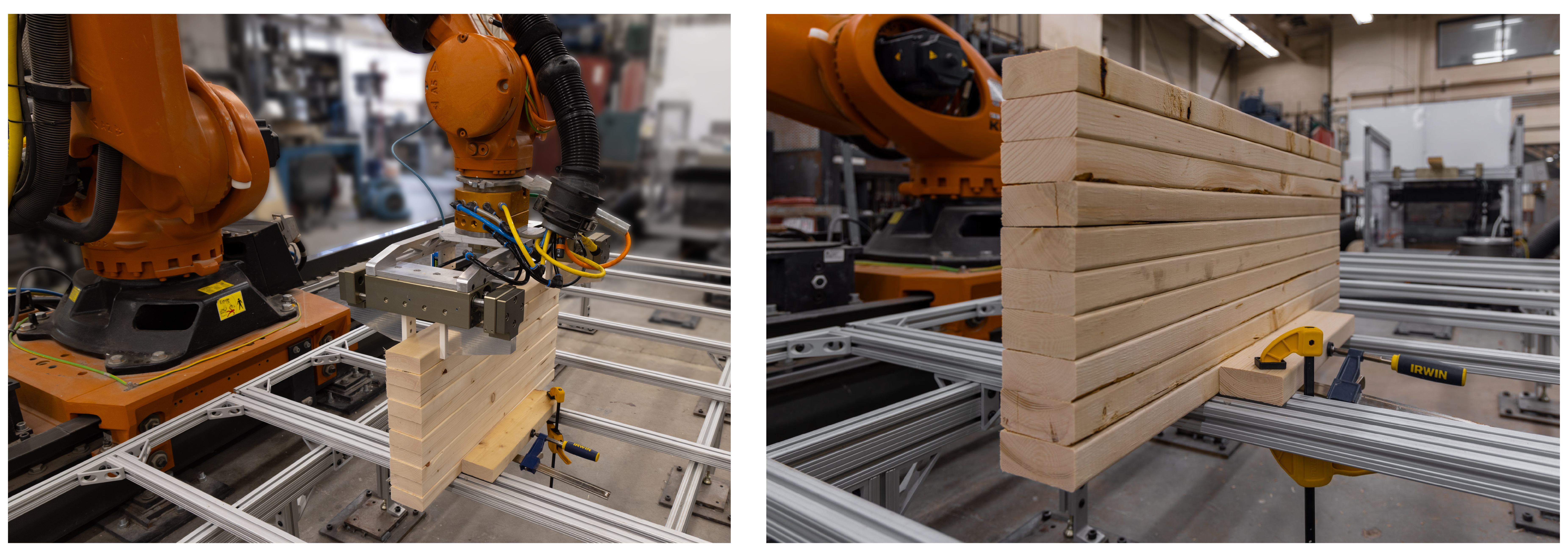
In the first experiment, the task was to fabricate a flat, 1-m-wide nail-laminated timber (NLT) panel by perpendicularly cutting, stacking, and fastening 10 elements cut from standard 2 × 4 dimensional lumber, alternating between the two robots. In applying the pose-based adaptive fabrication method, we tested two scenarios: (1) neither robot adapts (base case used for benchmarking, and (2) both robots utilizing the pose-based adaptive fabrication method (Fig. 5). While this assembly task is relatively simple, the experiment demonstrates the inherent additional deviations that can occur in a multi-robot assembly system due to discrepancies of their world frames, and how we can correct for them within a restricted number of degrees of freedom (planar translation and rotation).
Topology-based adaptive fabrication
We also formalize an adaptive fabrication method for minimizing deviations at the joints between elements using the topology of the as-planned digital model. Here, we refer to topology as the relationship between elements within a subassembly and how elements must be fastened together to form a structural connection. This approach acknowledges that ensuring a proper connection with current as-built elements is more important than their absolute pose for many elements in an assembly task. For example, a stud in a timber wall frame should be flush with the wall's surface, and its ends should be cut flat against the top and bottom plates. The stud’s pose has a small degree of freedom within these constraints. We first formalize the cut parameters for an element. Then, we scan a patch of the as-built structure, namely the contact surfaces where the element must interface. Finally, we update the element’s combined state (pose and cut parameters) to fit the scanned contact surfaces (Fig. 6). The overall control process is visualized in Fig. 7.
Wall module experiment
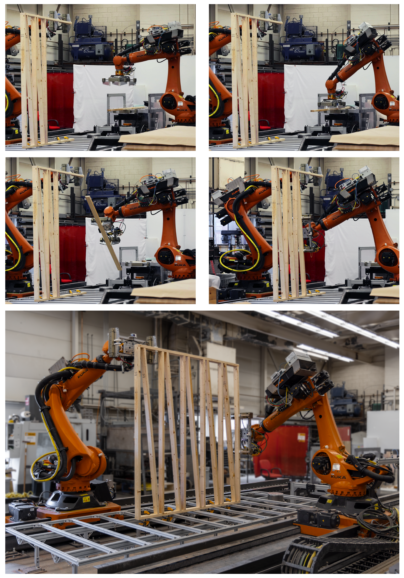
In the second experiment, the robotic setup was tasked to fabricate a full-scale spatial timber wall module (Fig. 8). The module consists of 13 elements connected via butt joints and measures 2.05 m long by 2.32 m tall. This experiment demonstrates the potential and necessity of multiple robots during fabrication to stabilize the in-progress subassembly during each step. In this type of assembly, it is common for the floor and top plate to have some material deformation, causing parts collision when inserting the studs without adaptation during robotic fabrication and interrupting the fabrication process. In this experiment, we utilized the developed topology-based adaptive fabrication method to ensure the assemblability of the wall module.
Results
After completing each subassembly in both experiments, we scan the as-built structure using the laser profiler end effector to collect a high-resolution point cloud, which is used in the following section to analyze the surface deviation from the as-planned digital model. The profile resolution of the laser profiler is 0.150 mm, and the depth resolution is 0.019 mm, with a linearity of ±0.01% of the measurement range. To scan the structure, we complete multiple passes of the laser profiler in overlapping bands. These partial scans are then stitched together using the recorded pose of the laser at each scan.
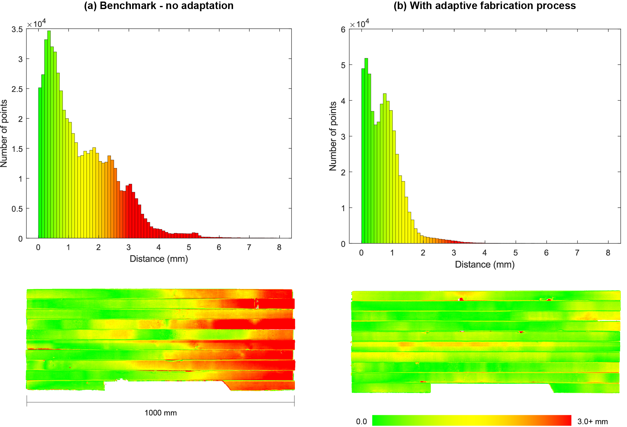
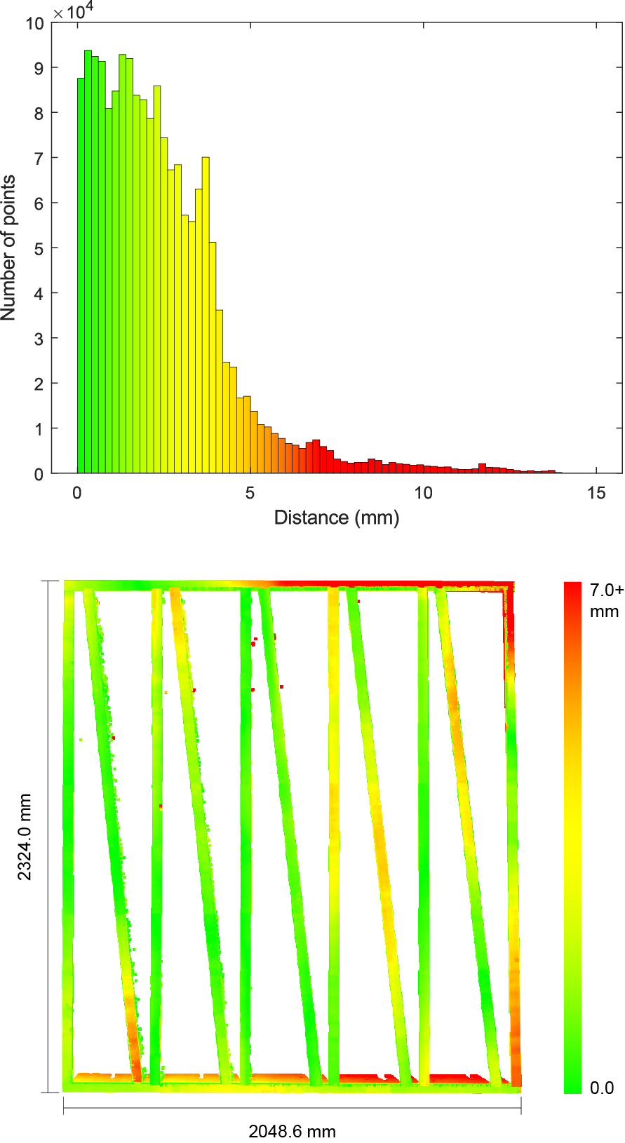
Fig. 9 shows surface deviations between the as-built NLT panel and the as-planned digital model for each scenario in a heat map and plotted in a histogram with a bin size of 0.1 mm. The average surface deviation of the benchmark scenario is 1.42 mm, with a median of 1.12 mm and a standard deviation of 1.16 mm. The average surface deviation of the adaptive scenario is 0.73 mm, with a median of 0.67 mm and a standard deviation of 0.58 mm. Fig. 10 shows the evaluated point cloud deviation between the final as-built wall module and the as-planned digital model. The deviations are visualized as a heat map and plotted in a histogram with a bin size of 0.2 mm. The average deviation is 2.43 mm, with a median of 2.06 mm and a standard deviation of 1.97 mm.
Conclusion
Our proposed framework relies on using the as-built subassembly as a localization target for self-calibration and fabrication adjustment, avoiding issues of calibrating to a common-world coordinate system using external measurement equipment. In particular, our developed pose-based adaptive method proved effective in decreasing deviations of the as-built NLT panel from its as-planned digital model for a cooperative assembly task performed by two robots. Furthermore, our topology-based adaptive method enabled the successful completion of a wall module, which was fabricated cooperatively by two robots. This research contributes to the body of knowledge required to facilitate flexible and accurate cooperative multi-robot construction at the building scale.
Acknowledgments
This research was supported by the National Science Foundation (NSF, Award No. 2128623) and the Taubman College of Architecture and Urban Planning (TCAUP) at the University of Michigan (U-M). Empirical physical prototyping research was conducted at the University of Michigan. The authors would like to thank Rachael Henry for her invaluable support at the TCAUP FABLab.
BibTeX
@article{adel2024feedback,
  title={Feedback-driven adaptive multi-robot timber construction},
  author={Adel, Arash and Ruan, Daniel and McGee, Wesley and Mozaffari, Salma},
  journal={Automation in Construction},
  volume={164},
  pages={105444},
  year={2024},
  publisher={Elsevier},
  url={https://doi.org/10.1016/j.autcon.2024.105444}
}